
How to Make Riveted Steel Grating?
First, arrange the cut flat steel and cross bars according to the spacing required by the design, then use a rivet gun or other riveting equipment to pass the rivets through the connecting holes of the flat steel and the crossbar, and deform the rivets by squeezing or hammering, so that the flat steel and the crossbar are firmly connected together.
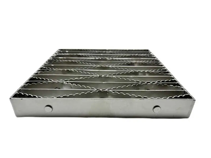
Riveted gratings are available in carbon steel, 6000 series aluminum, and 300 series stainless steel. These products are manufactured with bearing bars spaced 1-1/8” or 3/4” apart, with standard rivet spacing of 7” on center. Optional close rivet spacing of 3-1/2” on center is also available.
Standard serrations consist of the teeth of the grating bar being raised slightly above the top plane of the bearing bar during assembly. Alternatively, the user may specify 100% serrations, where both the bearing bar and cross member are provided with serrations.
Specifications of Riveted Grating
-
Material: carbon steel, 6000 series aluminum, and 300 series stainless steels
-
Category: It can be divided into light duty and heavy duty riveted gratings by load bearing capacity.
-
Surface treatment: galvanized, painted or mill finished.
-
Surface type: smooth surface or serrated surface.
-
Standard: conform to ANSI/NAAMM STANDARD MBG 531.
-
Spacing Available: These products are manufactured with bearing bars spaced either 1-1/8″ or 3/4″ apart and the standard rivet spacing is 7″ on center.Optional close rivet spacing of 3-1/2″ on center is also available.
| Table 1: 18-R-7/3.5 (1-1/8″) Steel Load Table | |||||||||||||||
| Bearing Bar Size (inches) | Approx. Weight psf * | Maximum Pedestrian Span** | Load Types | Unsupported Span | |||||||||||
| 2′-0 | 2′-6 | 3′-0 | 3′-6 | 4′-0 | 4′-6 | 5′-0 | 5′-6 | 6′-0 | 6′-6 | 7′-0 | 8′-0 | ||||
| 3/4 × 3/16 | 7.8 | 4′-0″ | U | 613 | 392 | 272 | 200 | 153 | 121 | 98 | All loads and deflections are theoretical and based upon the gross sections of the bearing bars, using a fiber stress of 18,000 psi. | ||||
| D | 0.099 | 0.155 | 0.223 | 0.304 | 0.397 | 0.503 | 0.621 | The values are not intended to be absolute since the actual load | |||||||
| C | 613 | 490 | 409 | 350 | 306 | 272 | 245 | capacity will be affected by the slight variations in mill and manufacturing tolerances. | |||||||
| D | 0.079 | 0.124 | 0.179 | 0.243 | 0.318 | 0.402 | 0.497 | Grating for spans to the left of the heavy line have a deflection ≤ 1/4″ for uniform loads of 100 psf. | |||||||
| 1 × 1/8 | 7.6 | 4′-5″ | U | 726 | 465 | 323 | 237 | 182 | 144 | 116 | |||||
| D | 0.074 | 0.116 | 0.168 | 0.228 | 0.298 | 0.377 | 0.466 | ||||||||
| C | 726 | 581 | 484 | 415 | 363 | 323 | 291 | ||||||||
| D | 0.06 | 0.093 | 0.134 | 0.182 | 0.238 | 0.302 | 0.372 | ||||||||
| 1 × 3/16 | 9.4 | 4′-11″ | U | 1090 | 697 | 484 | 356 | 272 | 215 | 174 | 144 | U – uniform load in pounds/sq. ft. | |||
| D | 0.074 | 0.116 | 0.168 | 0.228 | 0.298 | 0.377 | 0.466 | 0.563 | C – concentrated load in pounds/ft. of grating width | ||||||
| C | 1090 | 872 | 726 | 623 | 545 | 484 | 436 | 396 | D – deflection in inches | ||||||
| D | 0.06 | 0.093 | 0.134 | 0.182 | 0.238 | 0.302 | 0.372 | 0.451 | |||||||
| 1-1/4 × 1/8 | 8.7 | 5′-3″ | U | 1135 | 726 | 504 | 371 | 284 | 224 | 182 | 150 | 126 | / | / | / |
| D | 0.06 | 0.093 | 0.134 | 0.182 | 0.238 | 0.302 | 0.372 | 0.451 | 0.536 | / | / | / | |||
| C | 1135 | 908 | 757 | 649 | 567 | 504 | 454 | 413 | 378 | / | / | / | |||
| D | 0.048 | 0.074 | 0.107 | 0.146 | 0.191 | 0.241 | 0.298 | 0.36 | 0.429 | / | / | / | |||
| 1-1/4 × 3/16 | 11 | 5′-10″ | U | 1702 | 1090 | 757 | 556 | 426 | 336 | 272 | 225 | 189 | 161 | / | / |
| D | 0.06 | 0.093 | 0.134 | 0.182 | 0.238 | 0.302 | 0.372 | 0.451 | 0.536 | 0.629 | / | / | |||
| C | 1702 | 1362 | 1135 | 973 | 851 | 757 | 681 | 619 | 567 | 524 | / | / | |||
| D | 0.048 | 0.074 | 0.107 | 0.146 | 0.191 | 0.241 | 0.298 | 0.36 | 0.429 | 0.504 | / | / | |||
| 1-1/2 × 1/8 | 9.9 | 6′-0″ | U | 1634 | 1046 | 726 | 534 | 409 | 323 | 262 | 216 | 182 | 155 | 133 | 102 |
| D | 0.05 | 0.078 | 0.112 | 0.152 | 0.199 | 0.251 | 0.31 | 0.376 | 0.447 | 0.524 | 0.608 | 0.794 | |||
| C | 1634 | 1307 | 1090 | 934 | 817 | 726 | 654 | 594 | 545 | 503 | 467 | 409 | |||
| D | 0.04 | 0.062 | 0.089 | 0.122 | 0.159 | 0.201 | 0.248 | 0.3 | 0.358 | 0.42 | 0.487 | 0.636 | |||
| 1-1/2 × 3/16 | 12.5 | 6′-8″ | U | 2451 | 1569 | 1090 | 800 | 613 | 484 | 392 | 324 | 272 | 232 | 200 | 153 |
| D | 0.05 | 0.078 | 0.112 | 0.152 | 0.199 | 0.251 | 0.31 | 0.376 | 0.447 | 0.524 | 0.608 | 0.794 | |||
| C | 2451 | 1961 | 1634 | 1401 | 1226 | 1090 | 981 | 891 | 817 | 754 | 700 | 613 | |||
| D | 0.04 | 0.062 | 0.089 | 0.122 | 0.159 | 0.201 | 0.248 | 0.3 | 0.358 | 0.42 | 0.487 | 0.636 | |||
| 1-3/4 × 3/16 | 14.2 | 7′-6″ | U | 3337 | 2135 | 1483 | 1090 | 834 | 659 | 534 | 441 | 371 | 316 | 272 | 209 |
| D | 0.043 | 0.067 | 0.096 | 0.13 | 0.17 | 0.215 | 0.266 | 0.322 | 0.383 | 0.45 | 0.521 | 0.681 | |||
| C | 3337 | 2669 | 2224 | 1907 | 1668 | 1483 | 1335 | 1213 | 1112 | 1027 | 953 | 834 | |||
| D | 0.034 | 0.053 | 0.077 | 0.104 | 0.136 | 0.172 | 0.213 | 0.257 | 0.306 | 0.36 | 0.417 | 0.545 | |||
| 2 × 3/16 | 16.8 | 8′-3″ | U | 4358 | 2789 | 1937 | 1423 | 1090 | 861 | 697 | 576 | 484 | 413 | 356 | 272 |
| D | 0.037 | 0.058 | 0.084 | 0.114 | 0.149 | 0.189 | 0.233 | 0.282 | 0.335 | 0.393 | 0.456 | 0.596 | |||
| C | 4358 | 3486 | 2905 | 2490 | 2179 | 1937 | 1743 | 1585 | 1453 | 1341 | 1245 | 1090 | |||
| D | 0.03 | 0.047 | 0.067 | 0.091 | 0.119 | 0.151 | 0.186 | 0.225 | 0.268 | 0.315 | 0.365 | 0.477 | |||
| 2-1/4 × 3/16 | 18.3 | 9′-0″ | U | 5515 | 3530 | 2451 | 1801 | 1379 | 1090 | 883 | 729 | 613 | 522 | 450 | 345 |
| D | 0.033 | 0.052 | 0.074 | 0.101 | 0.132 | 0.168 | 0.207 | 0.25 | 0.298 | 0.35 | 0.406 | 0.53 | |||
| C | 5515 | 4412 | 3677 | 3152 | 2758 | 2451 | 2206 | 2006 | 1839 | 1697 | 1576 | 1379 | |||
| D | 0.026 | 0.041 | 0.06 | 0.081 | 0.106 | 0.134 | 0.166 | 0.2 | 0.238 | 0.28 | 0.324 | 0.424 | |||
| 2-1/2 × 3/16 | 19.9 | 9′-9″ | U | 6809 | 4358 | 3026 | 2223 | 1702 | 1345 | 1090 | 900 | 757 | 645 | 556 | 426 |
| D | 0.03 | 0.047 | 0.067 | 0.091 | 0.119 | 0.151 | 0.186 | 0.225 | 0.268 | 0.315 | 0.365 | 0.477 | |||
| C | 6809 | 5447 | 4540 | 3891 | 3405 | 3026 | 2724 | 2476 | 2270 | 2095 | 1946 | 1702 | |||
| D | 0.024 | 0.037 | 0.054 | 0.073 | 0.095 | 0.121 | 0.149 | 0.18 | 0.215 | 0.252 | 0.292 | 0.381 | |||
| * Weight per square foot based upon rivets spaced at 7″ on center. Add .40 psf for 3-1/2″ rivet centers. | |||||||||||||||
| ** Maximum pedestrian load is defined as a 100# uniform load with deflection ≤ 1/4 inch. The 1/4″ maximum deflection criteria is considered consistent with pedestrian comfort, but may be exceeded for other loading conditions at the discretion of the specifying authority. | |||||||||||||||
| Table 2: 12-R-7/3.5 (3/4″) Steel Load Table | |||||||||||||||
| Bearing Bar Size (inches) | Approx. Weight psf * | Maximum Pedestrian Span** | Load Types | Unsupported Span | |||||||||||
| 2′-0 | 2′-6 | 3′-0 | 3′-6 | 4′-0 | 4′-6 | 5′-0 | 5′-6 | 6′-0 | 6′-6 | 7′-0 | 8′-0 | ||||
| 3/4 × 3/16 | 10.7 | 4′-4″ | U | 858 | 549 | 381 | 280 | 215 | 170 | All loads and deflections are theoretical and based upon the gross sections of the bearing bars, using a fiber stress of 18,000 psi. | |||||
| D | 0.099 | 0.155 | 0.223 | 0.304 | 0.397 | 0.503 | The values are not intended to be absolute since the actual load | ||||||||
| C | 858 | 686 | 572 | 490 | 429 | 381 | capacity will be affected by the slight variations in mill and manufacturing tolerances. | ||||||||
| D | 0.079 | 0.124 | 0.179 | 0.243 | 0.318 | 0.402 | Grating for spans to the left of the heavy line have a deflection ≤ 1/4″ for uniform loads of 100 psf. | ||||||||
| 1 × 3/16 | 12.8 | 5′-4″ | U | 1525 | 976 | 678 | 498 | 381 | 301 | 244 | 202 | U – uniform load in pounds/sq. ft. | |||
| D | 0.074 | 0.116 | 0.168 | 0.228 | 0.298 | 0.377 | 0.466 | 0.563 | C – concentrated load in pounds/ft. of grating width | ||||||
| C | 1525 | 1220 | 1017 | 872 | 763 | 678 | 610 | 555 | D – deflection in inches | ||||||
| D | 0.06 | 0.093 | 0.134 | 0.182 | 0.238 | 0.302 | 0.372 | 0.451 | |||||||
| 1-1/4 × 3/16 | 15 | 6′-4″ | U | 2383 | 1525 | 1059 | 778 | 596 | 471 | 381 | 315 | 265 | / | / | / |
| D | 0.06 | 0.093 | 0.134 | 0.182 | 0.238 | 0.302 | 0.372 | 0.451 | 0.536 | / | / | / | |||
| C | 2383 | 1907 | 1589 | 1362 | 1192 | 1059 | 953 | 867 | 794 | / | / | / | |||
| D | 0.048 | 0.074 | 0.107 | 0.146 | 0.191 | 0.241 | 0.298 | 0.36 | 0.429 | / | / | / | |||
| 1-1/2 × 3/16 | 17.1 | 7′-3″ | U | 3432 | 2196 | 1525 | 1121 | 858 | 678 | 549 | 454 | 381 | 325 | 280 | 215 |
| D | 0.05 | 0.078 | 0.112 | 0.152 | 0.199 | 0.251 | 0.31 | 0.376 | 0.447 | 0.524 | 0.608 | 0.794 | |||
| C | 3432 | 2745 | 2288 | 1961 | 1716 | 1525 | 1373 | 1248 | 1144 | 1056 | 981 | 858 | |||
| D | 0.04 | 0.062 | 0.089 | 0.122 | 0.159 | 0.201 | 0.248 | 0.3 | 0.358 | 0.42 | 0.487 | 0.636 | |||
| 1-3/4 × 3/16 | 19.4 | 8′-2″ | U | 4671 | 2989 | 2076 | 1525 | 1168 | 923 | 747 | 618 | 519 | 442 | 381 | 292 |
| D | 0.043 | 0.067 | 0.096 | 0.13 | 0.17 | 0.215 | 0.266 | 0.322 | 0.383 | 0.45 | 0.521 | 0.681 | |||
| C | 4671 | 3737 | 3114 | 2669 | 2336 | 2076 | 1868 | 1699 | 1557 | 1437 | 1335 | 1168 | |||
| D | 0.034 | 0.053 | 0.077 | 0.104 | 0.136 | 0.172 | 0.213 | 0.257 | 0.306 | 0.36 | 0.417 | 0.545 | |||
| 2 × 3/16 | 22.9 | 9′-0″ | U | 6101 | 3905 | 2712 | 1992 | 1525 | 1205 | 976 | 807 | 678 | 578 | 498 | 381 |
| D | 0.037 | 0.058 | 0.084 | 0.114 | 0.149 | 0.189 | 0.233 | 0.282 | 0.335 | 0.393 | 0.456 | 0.596 | |||
| C | 6101 | 4881 | 4067 | 3486 | 3050 | 2712 | 2440 | 2219 | 2034 | 1877 | 1743 | 1525 | |||
| D | 0.03 | 0.047 | 0.067 | 0.091 | 0.119 | 0.151 | 0.186 | 0.225 | 0.268 | 0.315 | 0.365 | 0.477 | |||
| 2-1/4 × 3/16 | 25 | 9′-10″ | U | 7721 | 4942 | 3432 | 2521 | 1930 | 1525 | 1235 | 1021 | 858 | 731 | 630 | 483 |
| D | 0.033 | 0.052 | 0.074 | 0.101 | 0.132 | 0.168 | 0.207 | 0.25 | 0.298 | 0.35 | 0.406 | 0.53 | |||
| C | 7721 | 6177 | 5148 | 4412 | 3861 | 3432 | 3089 | 2808 | 2574 | 2376 | 2206 | 1930 | |||
| D | 0.026 | 0.041 | 0.06 | 0.081 | 0.106 | 0.134 | 0.166 | 0.2 | 0.238 | 0.28 | 0.324 | 0.424 | |||
| 2-1/2 × 3/16 | 27.2 | 10′-8″ | U | 9533 | 6101 | 4237 | 3113 | 2383 | 1883 | 1525 | 1261 | 1059 | 903 | 778 | 596 |
| D | 0.03 | 0.047 | 0.067 | 0.091 | 0.119 | 0.151 | 0.186 | 0.225 | 0.268 | 0.315 | 0.365 | 0.477 | |||
| C | 9533 | 7626 | 6355 | 5447 | 4766 | 4237 | 3813 | 3466 | 3178 | 2933 | 2724 | 2383 | |||
| D | 0.024 | 0.037 | 0.054 | 0.073 | 0.095 | 0.121 | 0.149 | 0.18 | 0.215 | 0.252 | 0.292 | 0.381 | |||
| * Weight per square foot based upon rivets spaced at 7″ on center. Add .40 psf for steel products with 3-1/2″ rivet centers. | |||||||||||||||
| ** Maximum pedestrian load is defined as a 100# uniform load with deflection ≤ 1/4 inch. The 1/4″ maximum deflection criteria is considered consistent with pedestrian comfort, but may be exceeded for other loading conditions at the discretion of the specifying authority. | |||||||||||||||


Features of Riveted Grating
-
Resistant to acid and alkali corrosion
-
High strength and robust structure
-
Good drainage function
-
High load-bearing capacity and deformation resistance
-
Serrated surface design offers good anti-slip performance
-
Easy to install and maintain
Applications of Riveted Grating
Light Duty Riveted Grating:
-
Floor.
-
Walkway.
-
Bridge decking.
-
Stair treads.
-
Well cover.
Heavy Duty Riveted Grating:
-
Bridges decking and highway trenches
-
Airport ramps
-
Ramps and docks
-
Commercial entrances
-
Trench gratings


